While I was playing with a 3-axis magnetometer (and having built rockets before) I had this idea for sensing the moment a rocket reaches apogee so that optimum parachute deployment is ensured.
Commercial solutions that I’ve seen use a barometer to sense the altitude (combined with an accelerometer for reliable operation) and are complex and expensive, so I thought: we know that the rocket will be tangent to its trajectory all the time so at apogee the rocket will be horizontal and then it will point the nose down, so why not take the rocket inclination as indication of apogee?
Using a magnetometer and the Earth’s magnetic field as reference should be a reliable way to determine the orientation, since it is not affected by the (lack of) G forces as an accelerometer sensing the gravitational field would be for example, provided the magnetic field vector is as vertical as possible.
How does it really work?
By having one of the magnetic sensor axis parallel to the rocket longitudinal axis and taking the axis reading, we can know the rocket is pointing up when the value is positive and pointing down when the value is negative.
To be more precise, we can know on which side of the plane that is perpendicular to the magnetic field vector the rocket is oriented.

B is the Earth magnetic field vector (about 60 degrees inclination). The thin blue line is the side view of the plane perpendicular to B. Bz is the rocket magnetomer axis reading, which is positive above the plane and negative below the plane.
The rocket will be considered pointing up while it is inside the positive 60 degrees cone and pointing down while it is inside the negative 60 degrees cone.
The zone in between the cones is uncertain and can cause both a “pointing up” reading and “pointing down” reading, depending in which direction the rocket is tipping over relative to the North (magnetic declination).
In places where the magnetic field is perfectly vertical (inclination is 90 degrees at the magnetic North and South poles) there is no uncertainty zone, while in places where the magnetic field is horizontal (at Equator) all positions fall into the uncertainty zone, meaning that this method will not work.
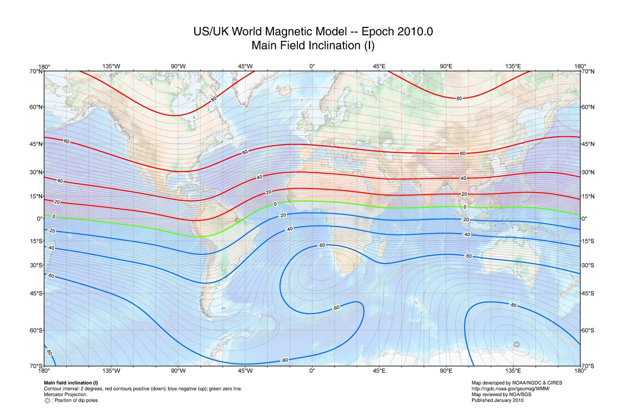
As you can see, across all US, Canada, Europe, Russia, Japan, South Africa and almost all Australia territory, the inclination is above 45 degrees.
We want the uncertainty zone to be as small as possible, therefore the magnetic inclination to be high.
Check for a minimum magnetic inclination of 45 degrees in the intended geographical area of operation:
A quick and dirty prototype with an Arduino and HMC5883L: https://www.youtube.com/watch?v=MZUnnsldayk
Now the pcb version with all the stuff needed to actually run inside a rocket: Hg switch to prevent the magnetometer to trigger from field perturbations on the ground (especially from the metal launch bar) power MOSFET for igniting the fuse and voltage divider for measuring the resistance of the fuse.
I used an ATtiny85 (same as tiny13 that I had available in Eagle but with hardware i2c support) because of its small size, while being powerful enough for this purpose.

Despite the 5V lines in the schematic, I run everything from a 1 cell Li-Po battery (3.3-4.2V) without any regulator because it is simply not needed. The MCU runs down to about 2.7V and the internal oscillator is stable enough given that millisecond accuracy is not needed.

The switch should be open when the rocket is tilted downwards (contacts towards tail) but the program can be adapted for the other way around.
Any mercury switch should work but I would avoid the big ones and glass casing to prevent breakage and toxic spill in case of an accident.

I know it looks ugly and unsafe but trust me I’ve checked all the solder joints and possible short circuit points under high magnifying lens and it’s alright.
You can make a proper PCB if you want, I just didn’t feel it’s worth it for only one piece.
Also, in case you’re wondering why I’ve used some SMD parts, it’s just because that’s what I had lying around with the suitable values.

If you’re still using the crappy Arduino IDE, do yourself a favor and use Sublime Text with the stino plugin https://github.com/Robot-Will/Stino
For the programming I’ve used some existing Arduino-tiny cores and an i2c library for tiny85.
WARNING: I cannot guarantee this code is free of bugs!!! Therefore I am not responsible for any injury or damage to property that might arise due to failures!
Make sure you understand what you are doing!
Turning on sequence:
- power-up with the nose oriented down (Hg switch in open position) and wait 1s;
-if the fuse is not properly connected (high resistance) or the nose is tilted up then multiple short tones are emitted; turn off and check connections;
-if the fuse is ok then a single 1s long tone is emitted;
- tilt the nose up;
- wait 1s;
- tilt the nose down until a single short tone is emitted; if no tone is emitted then magnetometer is not working properly or there are strong magnetic perturbances in the area; turn off;
- wait 3min; use this time to mount the rocket onto the launch system;
- 5s long tone is emitted; now the system is armed; DO NOT TILT THE NOSE DOWN OR FUSE WILL BE FIRED;
Working sequence:
- the system engages once it senses negative acceleration for at least 1s(configurable); this should happen immediately after motor burnout;
- once ENGAGED the system waits for the nose to go down; this should happen close to apogee; if magnetometer fails to report nose down, the system will time out after 12s(configurable) from burnout;
- the system fires the fuse and parachute is deployed;
- continuous tone is emitted for 1h;
- 1s long tone once every 10s is emitted (to keep it going as much as possible on the battery);
- first byte: 1 if the microcontroller was engaged by the switch or 0 otherwise;
- second byte: 1 if the microcontroller detected magnetic trigger (nose down) or 0 if the trigger happened after timeout;
Possible logs:
- 0 0 – switch fail or other unexpected fail; parachute trigger was not expected;
- 1 0 – magnetometer fail or timeout value set too small; parachute trigger was expected;
- 1 1 – no fail; parachute trigger was expected at apogee;
