I’ll show you a proof of concept ABS that I built with very cheap parts. I designed and mounted it on the rear wheel of a bike with mechanical action disk brakes. While hydraulic action would have provided much better performance, it would have raised the building costs too much for my “playing” budget, so I sticked to the mechanical cable system.
If you don’t know what ABS is and how it operates, have a look at the video below from youtube user allegroracing:
Although the animation shows a car, exactly the same applies for motorcycles and bikes, with the mention that a locked wheel on a bike can be even more dangerous than on a car, especially if it’s the front wheel.
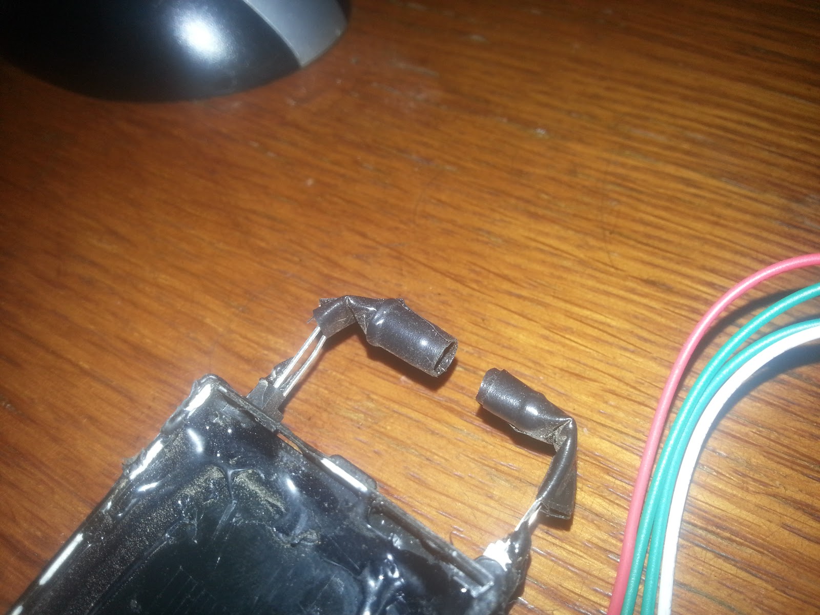
First, we need a sensor that will measure the wheel speed with very low latency. I did this with an IR LED phototransistor pair, making use of the brake disk that interrupts the IR beam 24 times per revolution due to the 24 cooling holes. At a wheel circumference of 2m, this will yield a minimum response distance of just under 9cm. Not bad, considering that the mechanical response time of the cable actuator is slow and it will turn out to be the bottleneck in the final response time/distance of the ABS system.

Now we need an actuator that will unlock the wheel as soon as the sensor detects that it locked after braking too hard. This can be accomplished in many ways, also depending on whether the action is cable or hydraulic based.
Given the cable system that I had, I used a simple, parallel mechanism that should be fairly robust*.
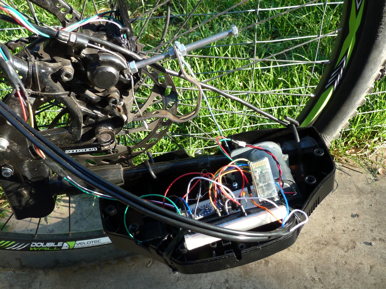
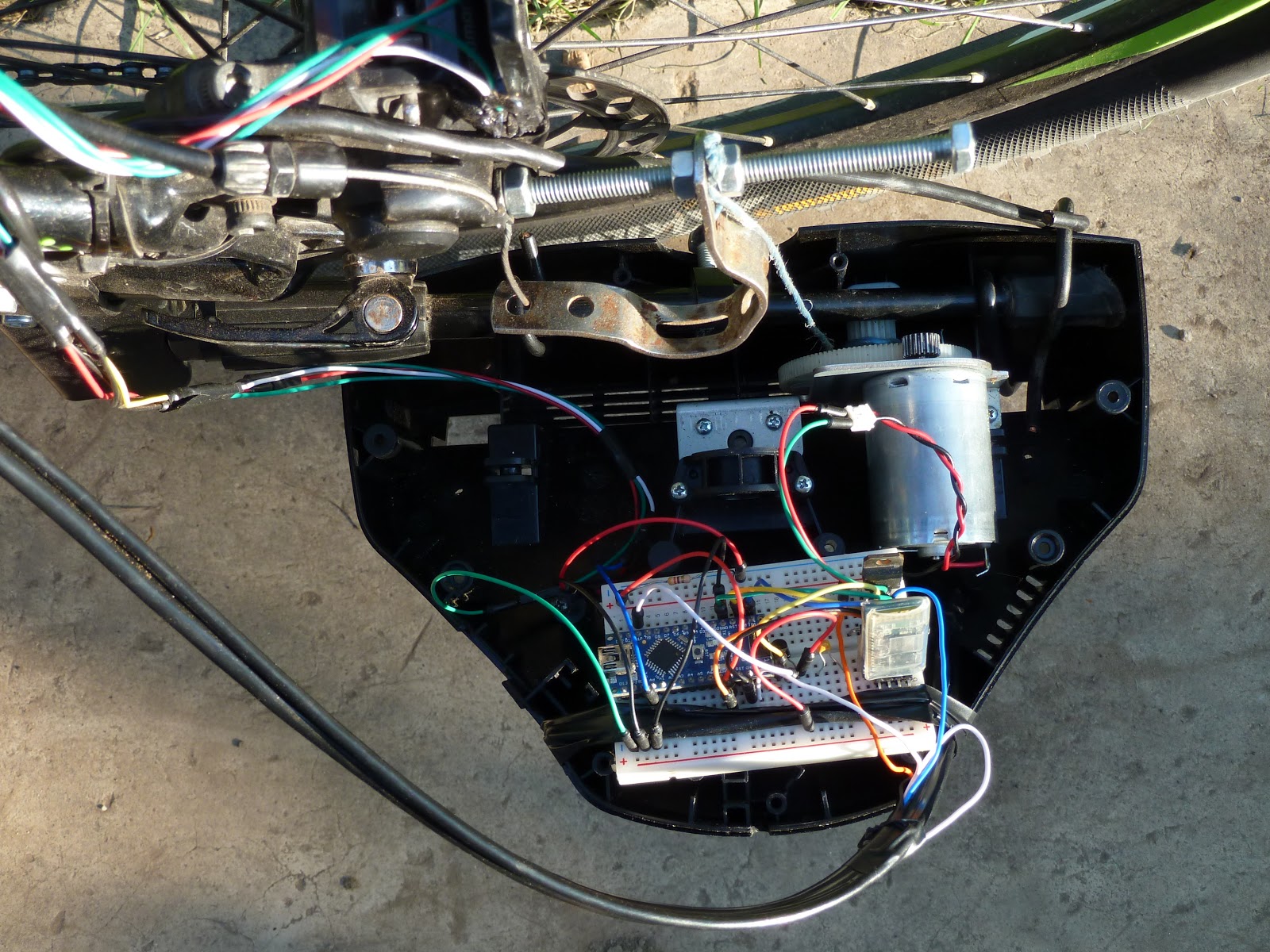
When you pull the brake lever, the cable will rotate the brake caliper shaft to the left, tightening the disk and applying brake. If you brake too hard for the surface that you’re on, the ABS engages – the caliper shaft is rotated to the right with the lever pulled by a geared motor through a strong multifilar nylon thread. This will loosen the brake caliper until the wheel starts moving back. As an inevitable effect, it will also push back the front brake lever and you will feel it at hand.
Once the wheel starts moving, the ABS disengages, leaving your hand pressure to get back to the caliper, increasing the brake force. If it locks again, the sequence is repeated as long as you need to brake. This cycle happens several times per second, keeping the brake force near the maximum threshold.
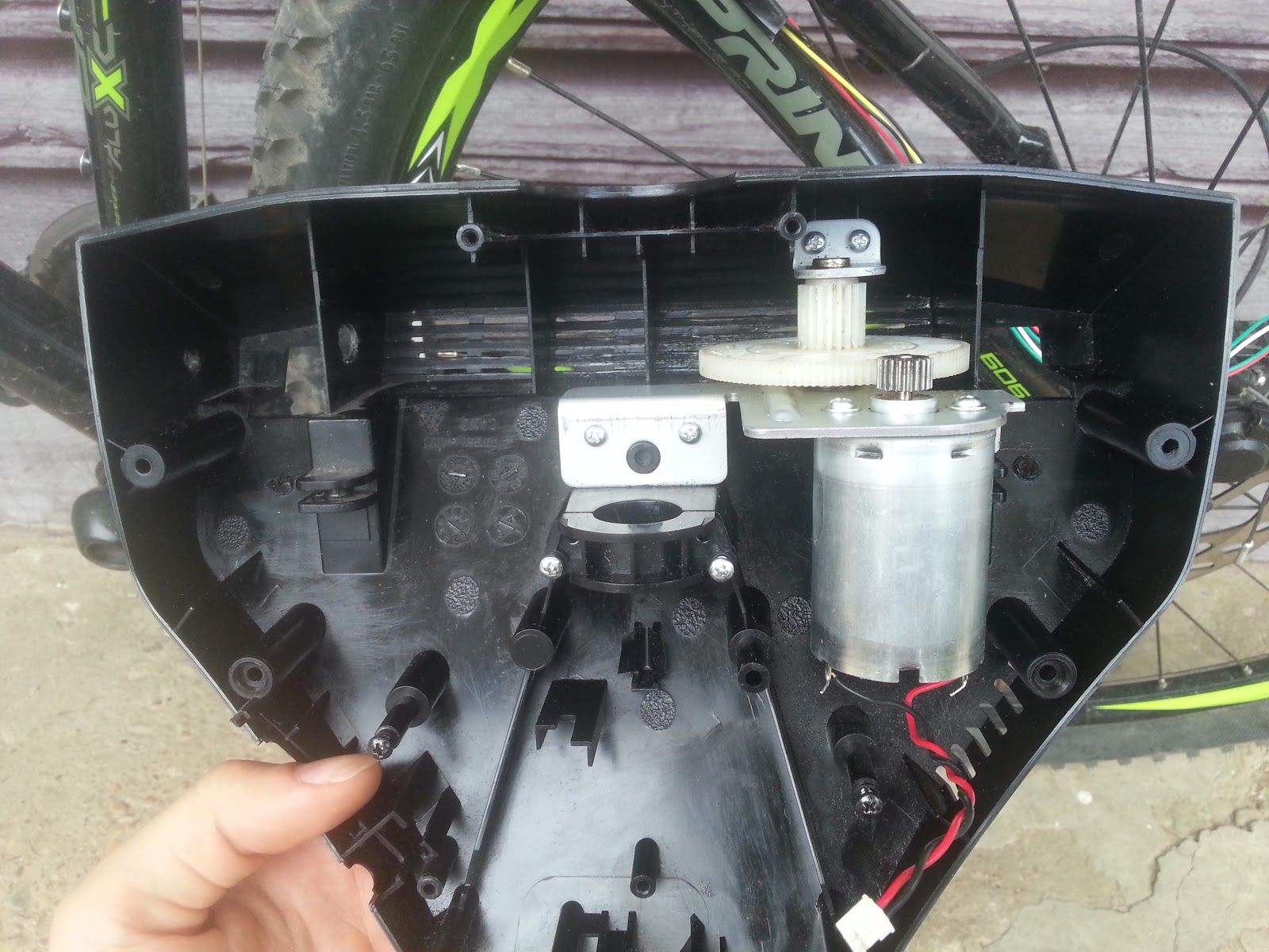
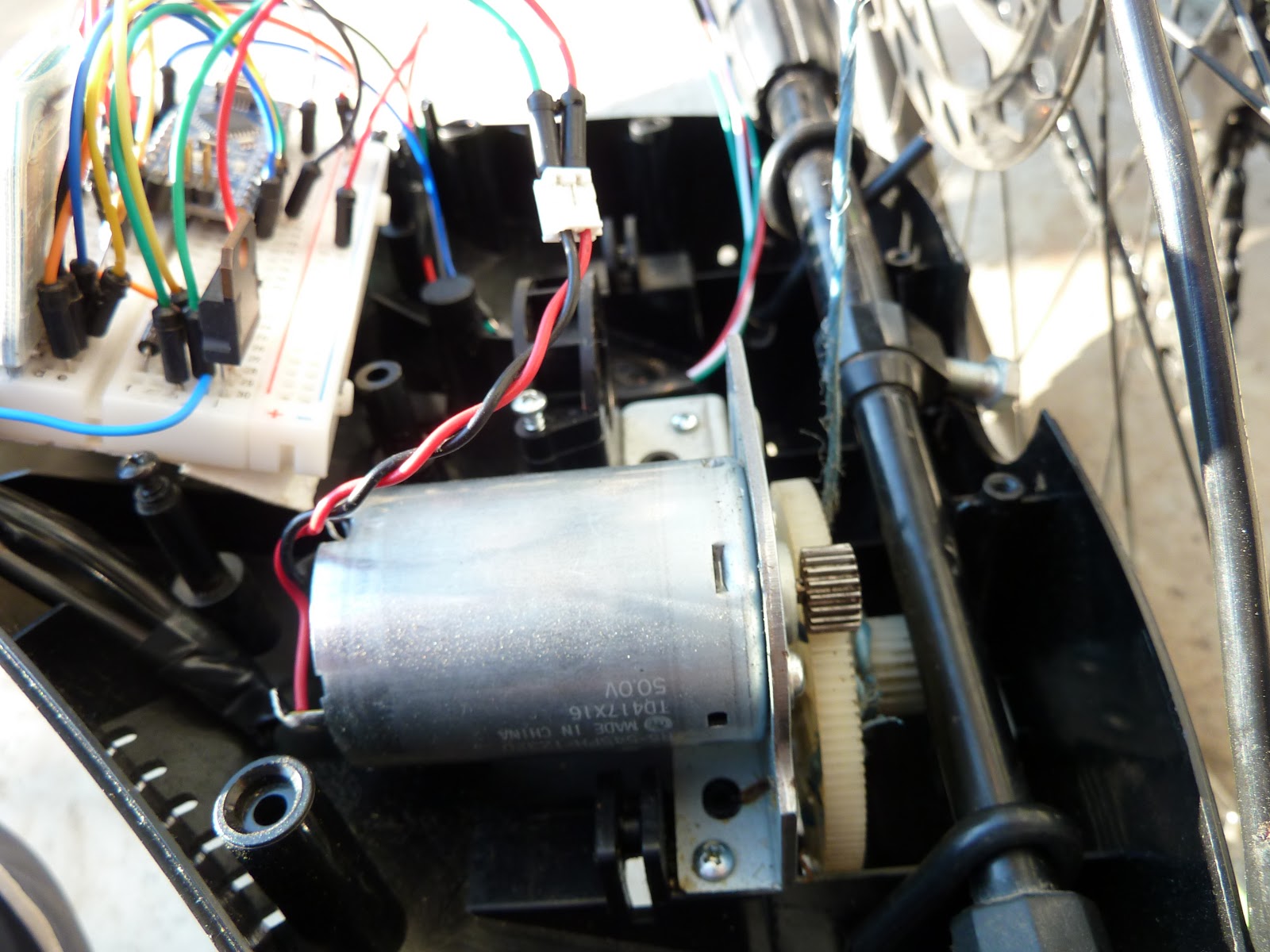
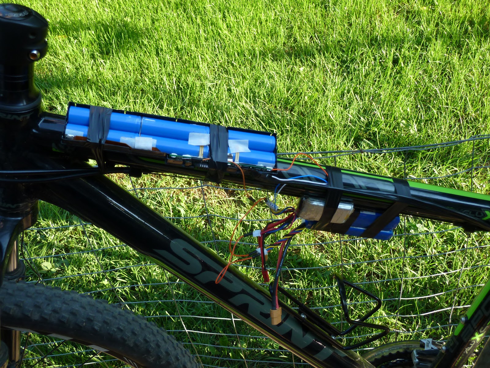
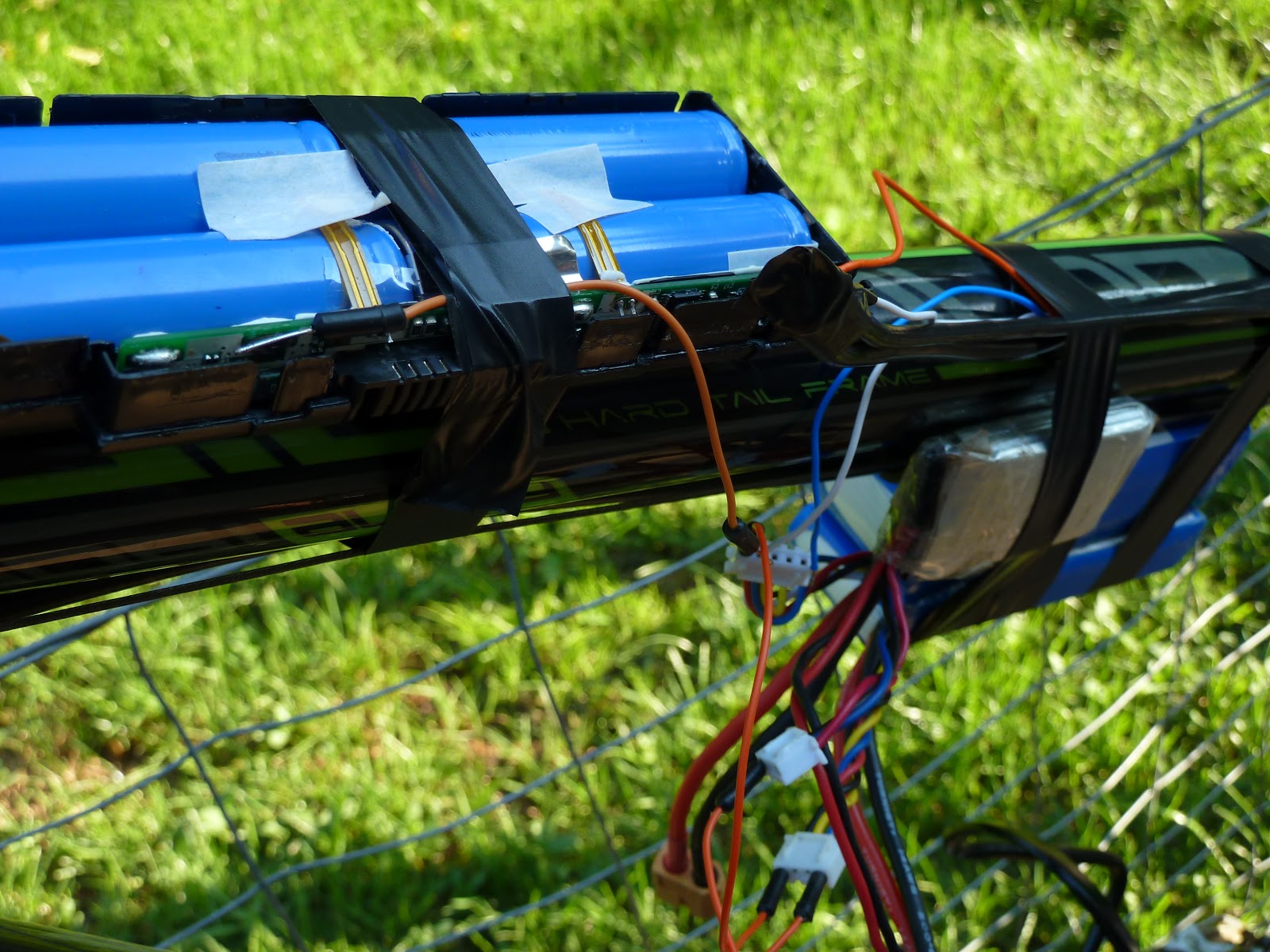
The geared motor mechanism that I used is from a Logitech force feedback gaming wheel, featuring a 50V 1A(stall current) Mabuchi motor. The high voltage requirement of the motor makes it difficult to power but luckily I had 12 lipo cells to put in series and a 100V power MOSFET to switch the motor. Power to the arduino comes from a 2 cell tap in the “pack”. I once accidentally powered it from 5 lipo cells and the input regulator burned bypass mode, burning the microcontroller as well, so be careful! The stated 20V input limit is tight! Perhaps the Chinese manufacturer used a cheaper, lower max input voltage regulator.
I adjusted the length of the brake caliper lever (that is pulled by the motor) by trial and error to get the optimum torque and speed given the motor and gear power characteristics.
Time for the video now, with the ABS closeup and testing on the road!
As you can see, the brake modulation rate is roughly 4 Hz, independent on the ground speed. At 15km/h the maximum modulation rate (limited by the sensor) should be 50 Hz, so it is obvious that the slow mechanical response time is the bottleneck (cable springiness and friction, low actuator motor power).
While it is certainly not on par with commercial ABS solutions on motorcycles and cars, it provides a decent amount of performance and safety.
* What I mean by robustness is that if the system is not powered or the batteries died, you will still be able to use the brake exactly like before, just without the anti-locking function.
Of course, there is still the possibility that a software bug will engage the ABS without the wheel actually locking, leaving you unable to pull the brake lever i.e. unable to brake. I do not have the resources as an individual to develop a safety certified system, so I mounted the ABS on the rear wheel only, leaving the front brake free for emergency situations.
If you follow these instructions to build your own system, you do so at your risk!
Code: bike_abs.ino
Here are some other ABS projects that I found on the internet, unfortunately with no technical details:
https://www.youtube.com/watch?v=phodYYQIl94
https://www.youtube.com/watch?v=LgTxmtkszdE

#1 by Sruthi on November 30, 2015 - 04:07
Tq very much for the info sir…as apart of our final year project we are trying to design this system,and we can’t figure it the mechanism for engaging and disengaging the gear mechanism …could you please explain us in detail..
LikeLike
#2 by zenondorin on December 5, 2015 - 11:56
If you look closely at the beginning of the video you can see how the mechanism works. The motor+gear is winding the nylon string. When it is energized, it rotates and pulls the string, rotating the caliper shaft to the right and loosening the brake. When it is not energized anymore, the manual brake lever is able to tighten back the brake caliper, unwinding the freewheeling motor.
LikeLike
#3 by Anonymous on February 4, 2016 - 18:30
thank u sir….can u please tell us anything about H-BRIDGE that u made on arduino ,basically we are from mechanical so we have no idea about it…..
LikeLike
#4 by zenondorin on February 4, 2016 - 19:52
It would be a good idea to also have someone that deals with the electronics in this case. Anyway, you can just buy a motor controller shield for arduino.
LikeLike
#5 by Jay Shah on June 12, 2016 - 14:27
Hello Sir, Amazing work, can you please give me the link for pwm header file?
LikeLike
#6 by zenondorin on July 22, 2016 - 19:59
The pwm header file is not needed at all, I forgot the #include there from previous experimentation, sorry.
LikeLike
#7 by Glenn Beck on July 19, 2017 - 19:19
Hi i interested in this project i have a hydraulic brake caliper what type of actuator is needed
Thanks
LikeLike
#8 by zenondorin on July 20, 2017 - 10:27
You can still try an electric motor, and you would have to attach it on the hand lever because I don’t see how you could tap into the system anywhere else.
LikeLike
#9 by Jatin Chauhan on August 8, 2018 - 16:06
Sir can we get the Circuit diagram of the system.
LikeLike
#10 by Timon Harmel on February 29, 2020 - 14:41
Hi is it possible to replace the dc motor with a servo ? and how can I change this in the sketch?
LikeLike