Archive for category Electronics
TempDoctor Reflow Oven Controller
Posted by zenondorin in Electronics, Hardware, Software on April 1, 2018
This is one project that I actually intended to put on kickstarter / indiegogo / crowdsupply, but after I had developed a prototype there was an unexpected shift in my career and now I don’t have the time to pursue this project anymore. I am just publishing my work and perhaps someone else could take the challenge to make it into a crowdfunding.
When I needed a reflow oven for my lab, there was nothing on the market that I liked. Without spending a couple of grands on a professional convection oven for prototyping and small batch assembly, the only available stuff was DIY kits that did not satisfy my performance requirements. Since I was sure I can make a good performance DIY kit with a sleek design which would cost only a few hundred bucks, I set to work.
TempDoctor module
The PCB was designed to fit an already existing case, as custom molding is too expensive for low-volume production. I found some kind of cheap mouse to be a good source of nice round and slim cases that can take a PCB as front panel (details in hardware files).


Convection oven integration
http://steba.com/product/baking/bake-oven-kb-14/?lang=en
The solid state relay simply replaces the original electromechanical relay and the controller is attached in place of the original temperature control knob.
I added extra thermal insulation with fiberglass sheets and aluminium tape. This particular configuration is able to ramp up with up to 1.5°C/s.


Functionality
- Superior control with fast set point stabilization and no overshoot
- Automatic parameter learning by step response analysis
- Manual setpoint with simple timer
- Automatic profiles – download via USB and save to memory (up to 8 profiles)
- Intuitive, fast and responsive operation with touch buttons
- Main display shows actual temperature, target temperature, rate of change in actual temperature, heater status (on/off), operation mode and timer count
Source code and hardware files
https://gitlab.com/dorinclisu/oven-controller
The temperature control is not based on PID because this method leads to very poor performance in this application (large thermal inertia and delayed response).
I developed a control algorithm based on a first order approximation of the differential equations describing the thermodynamics of the oven, and it is fairly close to optimal control.
Hardware Lab Home Setup
Posted by zenondorin in Electronics, Hardware, Mechatronics on March 28, 2018
When you first tell your friends that you’ve designed and built an electronics product at home it sounds a bit odd, but not so much after you show them a professional lab in your little apartment balcony!


Capabilities
Power and Signal Generation
- Digital Power Supply: TENMA 72-10495, 30V 5A
- Signal Generator: Rigol DG1022, 25MHz 2ch
Measurement
- Oscilloscope: Rigol DS1054Z, 50MHz 4ch (extended to 100MHz)
- Logic Analyzer: Saleae 8CH 24MHz
- Multimeter: UNI-T UT71D, True RMS 100kHz, 10µV, 1nA, 1pF
- IR Thermometer: UNI-T UT302D, -32 to 1050°C
Soldering
- Soldering Station: Hakko FX-888D, 250-500°C 60W
- Hot Air Station: Atten 858D, 100-500°C 800W
- Reflow Oven: Self Made Smart Controller, 60-240°C 1200W
- Fume ventilation: Bench fan
- Fume extraction: Overhead kitchen hood with external exhaust
PCB Prototyping
- Printing: Lexmark MX310DN, 600dpi, 2 print masks per layer
- Boards: Presensitized Copper 2 layer FR4
- Curing Lamp: UV LED 30W, 3 to 5 min exposure
- Developer: Sodium Metasilicate
- Etchant: Sodium Persulfate
- Trace Width and Spacing: 6 mil (0.15mm)
Miscellaneous
- Passive components (through-hole / SMD 0603), Analog and Digital IC
- Passive tools, Breadboarding kits, Cables, Adapters, Connectors
- Modules: Bluetooth HC-06, Ultrasound HC-SR04, IMU mpu6050, Magneto HMC5883L, GPS, LCD n1100 / n5110, OLED ssd1306
- Development Boards: STM32F4, STM32F3, Arduino Micro, RF cc2530, BLE nRF51822
- Recycled Electronics: GSM modules, Video TX systems, Mechanical and Optical assemblies, Smartphones, etc.
- Medals on Display: Mathematics and Physics
While I’ve had several tools, devices and electronics at home to play with for more than 10 years, it was only last year that I setup a proper lab to do R&D work for IoT devices.
There are still several things which are lacking, like a proper drilling machine, LCR meter, VNA, but they aren’t very much needed at the moment so I’ll see how to prioritize my purchases.
You can also notice some RC models, like a self built flying wing and quadcopter, a commercial boat, and some control accessories like radio transmitter and FPV video helmet. I also have another self built plane and another commercial plane but I keep them in my bedroom since there’s not enough space.
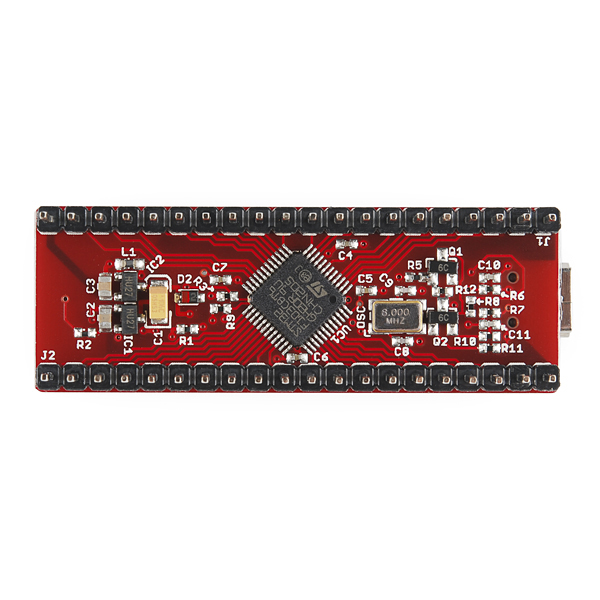
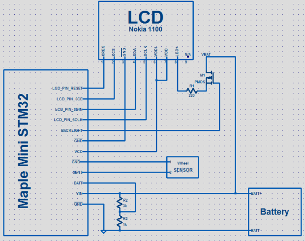
Bike computer with Nokia 1100 LCD
Posted by zenondorin in Hardware, Software on August 2, 2015
The biggest problem with cheap commercial speedometers is that they have volatile memory, so all data is gone after a battery replacement! There are already a couple of arduino bike speedometer projects, but none with a fully customizable matrix display.
I discovered that some old Nokia LCD’s are fairly easy to use, with a single SPI interface (non standard but it can be bit banged) and since I already had a Nokia 1100 handy, I set to make my own speedometer.

Soldering the wires on the small contact pins

Adding hotglue for strain relief, since the pins are really really fragile

Ready to be plugged in a breadboard!
I then hooked up the LCD to a leaflabs STM32 dev board mainly because the MCU is 3.3v (and the LCD would be damaged by 5v signal levels) but also because it has more RAM than the arduino nano to easily handle the display data.
http://www.aliexpress.com/item/leaflabs-Leaf-maple-mini-ARM-STM32-compatibility/32214664071.html
A voltage divider for low battery detection, light sensor and backlight FET are some additional components on the breadboard.
The rest of the hardware is also very simple, just like any available odometer on the market, a GPIO pin pulled up or down and connected to a reed switch which closes the circuit when the magnet on the wheel passes by.
This is mainly a software project and features:
- main speed ex. 28.1kph
- total distance ex. 6.1km
- total runtime ex. 09min (increments when speed > 0)
- average speed ex. 38kph
- maximum speed ex. 98kph (resets after auto power off)
- battery indicator ex. ~60%
- switched backlight
- data retention after complete power off
- setup navigation menu (wheel size, reset data)
- ??? add anything you want, like speed logging and graphing

The code is for the LeafLabs Maple IDE but you can adapt it for anything.
Navigation is done with only one button! One short click of the button means Change (of menu index or digit) and one long click means Select. I use the on board button (only on leaflabs) for this.
In the video you can see an external button that I use instead of the reed switch to simulate the wheel spinning.
Anti-lock Brake System for bikes
Posted by zenondorin in Mechatronics, Software on July 23, 2015
I’ll show you a proof of concept ABS that I built with very cheap parts. I designed and mounted it on the rear wheel of a bike with mechanical action disk brakes. While hydraulic action would have provided much better performance, it would have raised the building costs too much for my “playing” budget, so I sticked to the mechanical cable system.
If you don’t know what ABS is and how it operates, have a look at the video below from youtube user allegroracing:
Although the animation shows a car, exactly the same applies for motorcycles and bikes, with the mention that a locked wheel on a bike can be even more dangerous than on a car, especially if it’s the front wheel.
First, we need a sensor that will measure the wheel speed with very low latency. I did this with an IR LED phototransistor pair, making use of the brake disk that interrupts the IR beam 24 times per revolution due to the 24 cooling holes. At a wheel circumference of 2m, this will yield a minimum response distance of just under 9cm. Not bad, considering that the mechanical response time of the cable actuator is slow and it will turn out to be the bottleneck in the final response time/distance of the ABS system.


Now we need an actuator that will unlock the wheel as soon as the sensor detects that it locked after braking too hard. This can be accomplished in many ways, also depending on whether the action is cable or hydraulic based.
Given the cable system that I had, I used a simple, parallel mechanism that should be fairly robust*.


When you pull the brake lever, the cable will rotate the brake caliper shaft to the left, tightening the disk and applying brake. If you brake too hard for the surface that you’re on, the ABS engages – the caliper shaft is rotated to the right with the lever pulled by a geared motor through a strong multifilar nylon thread. This will loosen the brake caliper until the wheel starts moving back. As an inevitable effect, it will also push back the front brake lever and you will feel it at hand.
Once the wheel starts moving, the ABS disengages, leaving your hand pressure to get back to the caliper, increasing the brake force. If it locks again, the sequence is repeated as long as you need to brake. This cycle happens several times per second, keeping the brake force near the maximum threshold.


The geared motor mechanism that I used is from a Logitech force feedback gaming wheel, featuring a 50V 1A(stall current) Mabuchi motor. The high voltage requirement of the motor makes it difficult to power but luckily I had 12 lipo cells to put in series and a 100V power MOSFET to switch the motor. Power to the arduino comes from a 2 cell tap in the “pack”. I once accidentally powered it from 5 lipo cells and the input regulator burned bypass mode, burning the microcontroller as well, so be careful! The stated 20V input limit is tight! Perhaps the Chinese manufacturer used a cheaper, lower max input voltage regulator.


I adjusted the length of the brake caliper lever (that is pulled by the motor) by trial and error to get the optimum torque and speed given the motor and gear power characteristics.
Time for the video now, with the ABS closeup and testing on the road!
As you can see, the brake modulation rate is roughly 4 Hz, independent on the ground speed. At 15km/h the maximum modulation rate (limited by the sensor) should be 50 Hz, so it is obvious that the slow mechanical response time is the bottleneck (cable springiness and friction, low actuator motor power).
While it is certainly not on par with commercial ABS solutions on motorcycles and cars, it provides a decent amount of performance and safety.
* What I mean by robustness is that if the system is not powered or the batteries died, you will still be able to use the brake exactly like before, just without the anti-locking function.
Of course, there is still the possibility that a software bug will engage the ABS without the wheel actually locking, leaving you unable to pull the brake lever i.e. unable to brake. I do not have the resources as an individual to develop a safety certified system, so I mounted the ABS on the rear wheel only, leaving the front brake free for emergency situations.
If you follow these instructions to build your own system, you do so at your risk!
Code: bike_abs.ino
Here are some other ABS projects that I found on the internet, unfortunately with no technical details:
https://www.youtube.com/watch?v=phodYYQIl94
https://www.youtube.com/watch?v=LgTxmtkszdE
Magnetic Apogee Detector for rockets
Posted by zenondorin in Hardware, Software on October 26, 2014
While I was playing with a 3-axis magnetometer (and having built rockets before) I had this idea for sensing the moment a rocket reaches apogee so that optimum parachute deployment is ensured.
Commercial solutions that I’ve seen use a barometer to sense the altitude (combined with an accelerometer for reliable operation) and are complex and expensive, so I thought: we know that the rocket will be tangent to its trajectory all the time so at apogee the rocket will be horizontal and then it will point the nose down, so why not take the rocket inclination as indication of apogee?
Using a magnetometer and the Earth’s magnetic field as reference should be a reliable way to determine the orientation, since it is not affected by the (lack of) G forces as an accelerometer sensing the gravitational field would be for example, provided the magnetic field vector is as vertical as possible.
How does it really work?
By having one of the magnetic sensor axis parallel to the rocket longitudinal axis and taking the axis reading, we can know the rocket is pointing up when the value is positive and pointing down when the value is negative.
To be more precise, we can know on which side of the plane that is perpendicular to the magnetic field vector the rocket is oriented.

B is the Earth magnetic field vector (about 60 degrees inclination). The thin blue line is the side view of the plane perpendicular to B. Bz is the rocket magnetomer axis reading, which is positive above the plane and negative below the plane.
The rocket will be considered pointing up while it is inside the positive 60 degrees cone and pointing down while it is inside the negative 60 degrees cone.
The zone in between the cones is uncertain and can cause both a “pointing up” reading and “pointing down” reading, depending in which direction the rocket is tipping over relative to the North (magnetic declination).
In places where the magnetic field is perfectly vertical (inclination is 90 degrees at the magnetic North and South poles) there is no uncertainty zone, while in places where the magnetic field is horizontal (at Equator) all positions fall into the uncertainty zone, meaning that this method will not work.
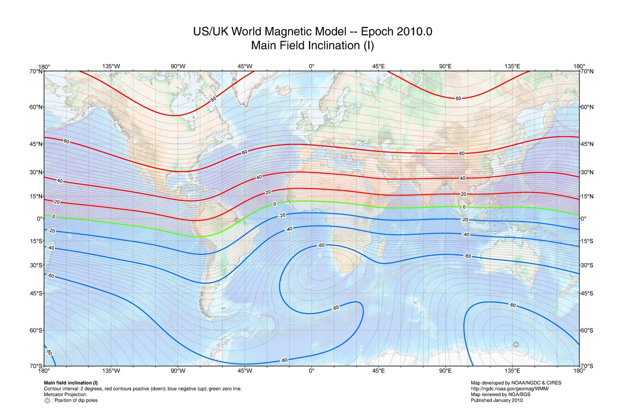
As you can see, across all US, Canada, Europe, Russia, Japan, South Africa and almost all Australia territory, the inclination is above 45 degrees.
We want the uncertainty zone to be as small as possible, therefore the magnetic inclination to be high.
Check for a minimum magnetic inclination of 45 degrees in the intended geographical area of operation:
A quick and dirty prototype with an Arduino and HMC5883L: https://www.youtube.com/watch?v=MZUnnsldayk
Now the pcb version with all the stuff needed to actually run inside a rocket: Hg switch to prevent the magnetometer to trigger from field perturbations on the ground (especially from the metal launch bar) power MOSFET for igniting the fuse and voltage divider for measuring the resistance of the fuse.
I used an ATtiny85 (same as tiny13 that I had available in Eagle but with hardware i2c support) because of its small size, while being powerful enough for this purpose.

Despite the 5V lines in the schematic, I run everything from a 1 cell Li-Po battery (3.3-4.2V) without any regulator because it is simply not needed. The MCU runs down to about 2.7V and the internal oscillator is stable enough given that millisecond accuracy is not needed.

The switch should be open when the rocket is tilted downwards (contacts towards tail) but the program can be adapted for the other way around.
Any mercury switch should work but I would avoid the big ones and glass casing to prevent breakage and toxic spill in case of an accident.

I know it looks ugly and unsafe but trust me I’ve checked all the solder joints and possible short circuit points under high magnifying lens and it’s alright.
You can make a proper PCB if you want, I just didn’t feel it’s worth it for only one piece.
Also, in case you’re wondering why I’ve used some SMD parts, it’s just because that’s what I had lying around with the suitable values.

If you’re still using the crappy Arduino IDE, do yourself a favor and use Sublime Text with the stino plugin https://github.com/Robot-Will/Stino
For the programming I’ve used some existing Arduino-tiny cores and an i2c library for tiny85.
WARNING: I cannot guarantee this code is free of bugs!!! Therefore I am not responsible for any injury or damage to property that might arise due to failures!
Make sure you understand what you are doing!
Turning on sequence:
- power-up with the nose oriented down (Hg switch in open position) and wait 1s;
-if the fuse is not properly connected (high resistance) or the nose is tilted up then multiple short tones are emitted; turn off and check connections;
-if the fuse is ok then a single 1s long tone is emitted;
- tilt the nose up;
- wait 1s;
- tilt the nose down until a single short tone is emitted; if no tone is emitted then magnetometer is not working properly or there are strong magnetic perturbances in the area; turn off;
- wait 3min; use this time to mount the rocket onto the launch system;
- 5s long tone is emitted; now the system is armed; DO NOT TILT THE NOSE DOWN OR FUSE WILL BE FIRED;
Working sequence:
- the system engages once it senses negative acceleration for at least 1s(configurable); this should happen immediately after motor burnout;
- once ENGAGED the system waits for the nose to go down; this should happen close to apogee; if magnetometer fails to report nose down, the system will time out after 12s(configurable) from burnout;
- the system fires the fuse and parachute is deployed;
- continuous tone is emitted for 1h;
- 1s long tone once every 10s is emitted (to keep it going as much as possible on the battery);
- first byte: 1 if the microcontroller was engaged by the switch or 0 otherwise;
- second byte: 1 if the microcontroller detected magnetic trigger (nose down) or 0 if the trigger happened after timeout;
Possible logs:
- 0 0 – switch fail or other unexpected fail; parachute trigger was not expected;
- 1 0 – magnetometer fail or timeout value set too small; parachute trigger was expected;
- 1 1 – no fail; parachute trigger was expected at apogee;
TGY 9X transmitter telemetry hack
Posted by zenondorin in Hardware on December 31, 2012
This is a simple hack to activate telemetry on the Turnigy 9x RC transmitter. Someone came with this idea on a forum and I have applied it in a different configuration: http://www.rcgroups.com/forums/showthread.php?t=1510047
Everything is explained in the video (make sure you have annotations on):
You will also need to to this cut on the other side of the board (I missed it from the video):

Computer soundcard tachometer
Posted by zenondorin in Hardware on December 31, 2012
Measure the angular speed of a propeller using an IR LED – Sensor, a soundcard and some windows software.
I have originally posted it on the forum: http://www.rcgroups.com/forums/showthread.php?t=1450032
